watch this first!
Before beginning your electrical system in your van conversion, we’ll run you through our standard electrical setup. You can download the electrical diagram as well as get all the electrical materials at the links below.
Please note: we do not allow electrical questions in the Facebook group as we do not want others giving unsafe advice. Please consult a professional for help on your electrical system.

Basic electrical diagram
This graphic shows the flow for our basic electrical system. CONSULT WITH AN ELECTRICAL ENGINEER TO FIND PROPER WIRE SIZING FOR YOUR SYSTEM.
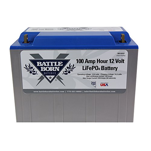
For this Diagram the battery bank is connected in Parallel. This means that the 500 AH of Battle Born Lithium Battery are connected in a 12v system. Batteries are connected Positive to Positive Terminal and Negative to Negative Terminal.
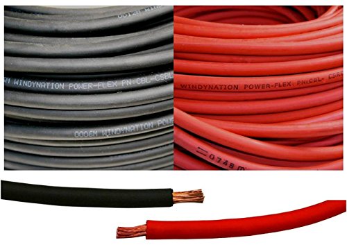
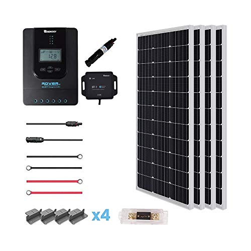
Solar panels connect to your solar controller. The positive wire(RED) then can run through a 50amp breaker and then to a positive busbar. The negative wire (BLACK) will run to the negative busbar and then to the SHUNT for the Victron BMV. The Shunt is then connected to the negative end of the battery bank.
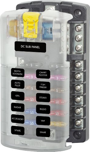
ALL 12v appliances will be connected to the 12v fuse block. We prefer to have 1 fuse block on each side of the van to prevent running so many wires through the ceiling. Each fuse block is then connected to the positive and negative busbars.
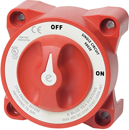
The Positive Bus Bar is connected to a 350 Amp Battery Switch. This allows the electrical system to be safely shut down for maintenance. This switch is connected to the positive end of the battery bank.
To power the AC/DC side of the power system the positive end of the battery bank is connected to the 300 Watt Victron Inverter Charger through a 500 Amp Heavy Duty Fuse. The Negative end of the battery bank is connected directly to the inverter.
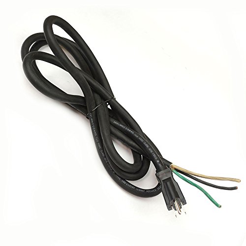
The Inverter is then connected to a 70 amp, 2 Space, Breaker box which is then connected to the 110v or 120v outlets. The Inverter is also connected to a 12/3 power cord to allow for shower power charging. The inverter remote is connected via a CAT 5 Cable.
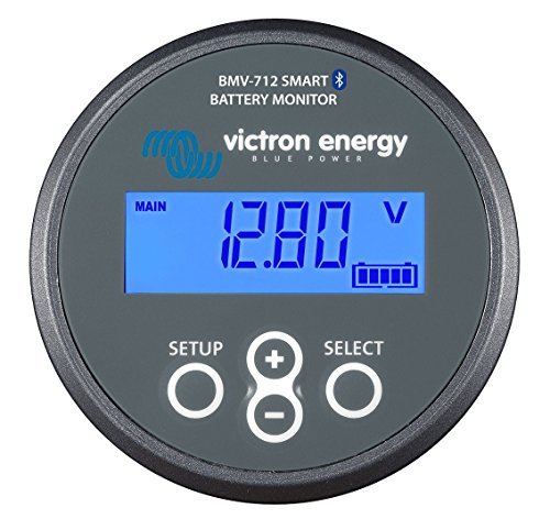
The Victron BMV Display is connected to the Shunt via a CAT 5 Cable. The Shunt is also connected to the positive end of the battery bank using a provided wire in the BMV kit.
electrical materials